

EN
Pulse analyzer dp5
Review
The Amptek DP5 is a state-of-the-art, high-performance, low-power pulse processor. It digitizes the signal from the preamplifier output, replacing the shaper and analyzer in traditional analog spectroscopy systems. The DP5 offers several distinct advantages over traditional systems, including improved performance (with very high resolution, high throughput, and increased stability), increased flexibility, low power consumption, small size, and low cost.
The DP5 implements pulse processing using a dedicated circuit. It includes an 8051 compatible microcontroller to control the device. Communication interfaces include RS232, USB, and Ethernet. Several general-purpose I/O lines are also available. The DP5 is designed for OEMs and for laboratory users who require customization options and are familiar with electronics.

Figure 1. DP5 Photo: 3.5" x 2.5"
Peculiarities
- 80 MHz ADC
- Replaces the shaper and analyzer
- Supports reset and feedback of preamps of any polarity
- MCS mode
- 16 SCA
- Configurable with charge sensitive preamplifier for use with PMT
- For OEM use in laboratory conditions
- Flexible in customization
Impulse Processing and MCA
- Trapezoidal pulse shape
- Peak time from 0.1 to 102.4 µs
- Duration from 0.05 to 51.2 µs
- 4000000 Hz
- Up to 8000 channels
Connection
- Interfaces: RS-232, USB, Ethernet
- Output to oscilloscope - for pulse control and adjustment
- PC software for data collection and control (including API)
- Many configurable additional inputs and outputs
Physical characteristics
- Low power: 600 mW
- Small size: 3.5 x 2.5 V
Application
-
X-ray and gamma detectors
-
Nuclear physics
-
Portable, battery operated system
-
OEM (as components)
-
Process management
-
Research and Education
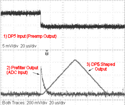
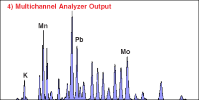
Figure 2. Footnote 1 above shows the signal at the input of DP5, which is the output from the resettable charge-sensitive preamplifier. The signal is then processed by an analog coarse filter, resulting in the signal shown in Figure footnote 2. This signal is digitized and then processed in DP5, resulting in the signal shown in footnote 3. Finally, DP5 produces the output spectrum shown in Figure 4.
| Gain | Combination of coarse and fine chain adjustment, smoothly adjustable from 0.84 to 127.5. | ||||||||||||||||
| Rough amplification | 16 logically arranged coarse tuning steps from x1.12 to X102.
|
||||||||||||||||
| Smooth gain | Smooth gain adjustable from 0.75 to 1.25, 10-bit resolution | ||||||||||||||||
| Full scale | 1000mV Input Pulse @ x1 Gain | ||||||||||||||||
| Stability | <20 ppm/°C (typical) | ||||||||||||||||
| ADC clock frequency | 20 or 80 MHz, 12-bit ADC (software) | ||||||||||||||||
| Pulse shape | Trapezoidal. A semi-amplifier with a Gaussian shaping time t has a peak time of 2.2t and is comparable in performance to a trapezoidal shape of the same peak time. | ||||||||||||||||
| Peak time | 30 software-selectable peak times ranging from 0.1 to 102 µs, corresponding to a semi-Gaussian shaping time of 0.05 to 45 µs. | ||||||||||||||||
| Flat Top Time | 16 software selectable values for each peak time (depending on peak time)> 0.05 µs. | ||||||||||||||||
| Maximum counting speed | With a peak time of 0.2 µs, 4 MHz periodic signal can be observed. | ||||||||||||||||
| Dead time in impulse | Dead time is 1.05 x peak time. No conversion time. | ||||||||||||||||
| Resolution time | 120 nsec | ||||||||||||||||
| Pulse superposition | The pulses are separated more when the resolution time is less than 120 ns and less when 1.05 x peak time. | ||||||||||||||||
| Restore scan line | Asymmetrical, 16 software selectable slew rate settings. |
MCA
| Number of channels | 256, 512, 1024, 2048, 4096, and 8192 channels. |
| Bytes per channel | 3 bytes (24 bits) - 16.7 million events |
| Preset collection time | from 10 ms to 466 days |
| Data transfer time | 1k channels in 5ms (USB) or 280ms (RS-232) |
| Conversion time | No |
| Data presentation | Time, total counters, counters in ROI, channel count |
| MCS time base | from 10 ms/channel to 300 sec/channel |
| External management of MCA | Input: Pulses are accepted only by external logic. Input can be active high or active low. |
| Counters | Channels with low event counts are accepted by the MCA, incoming events (channels with event counts above the threshold), events discarded by the selection logic, and an external event counter. |
Hardware
| Microprocessor | Silicon Labs 8051F340 8051-compatible core |
| External memory | 512kB SRAM |
| Firmware | Signal processing is programmable via firmware that can be upgraded in the field. |
Connection
| RS-232 | Standard RS-232 interface with speed up to 115.2 kBytes. |
| USB | USB 2.0 Full Speed (12 Mb/s) standard. |
| Ethernet | Standard 10Base-T |
Additional inputs and outputs
The main purpose of this connector is to expose logic signals that are not required for the primary processing of the DP5: spectra acquisition and transmission are done via the serial interface. These are typically "low level" logic signals associated with each pulse processed by the DP5. They are mainly used for synchronization of data collected by the DP5 and transmitted to external devices, as well as for the counting and timing outputs from the DP5.
| Single-channel analyzers (16 in total) |
Hardware Software 8 SCA, independent selection of LLDs and ULDs, selection between 8 parameters including INCOMING_COUNT, contact set, MCS_TIMEBASE etc. SCA software linked with internal counters and read by software. |
| Digital inputs | Two independent inputs, software selectable MCA_GATE, EXTERNAL_COUNTER general purpose I/O, two I/O lines for custom applications. |
| I/O | Two main purposes of I/O lines for user applications |
| Digital oscilloscope | Display the oscillogram on the computer. Software is selected to show the output waveform, ADC, etc. to help debug and optimize the configuration. |
Auxiliary connector contacts
| Contact # | Name | Contact # | Name |
| 1 | SCA1 | 2 | SCA2 |
| 3 | SCA3 | 4 | SCA4 |
| 5 | SCA5 | 6 | SCA6 |
| 7 | SCA7 | 8 | SCA8 |
| 9 | AUX_IN_1 | 10 | AUX_OUT_1 |
| 11 | AUX_IN_2 | 12 | AUX_OUT_2 |
| 13 | IO2 | 14 | IO3 |
| 15 | GND | 16 | GND |
Connection
| Analog input | The analog input accepts positive or negative pulses from a charge-sensitive preamplifier. Note: Can be configured with a charge-sensitive preamplifier for use with a PMT. For more information, contact Technoanalitpribor. 1x3 Molex part number 22-28-8032. |
| Nutrition | +5VDC Hirose MQ172-3PA (55) |
| RS232 | Standard 2.5mm headphone jack. |
| USB | Standard USB mini connector . |
| Ethernet | Standard Ethernet connector. |
| Auxiliary | 2x8 16-pin 2mm (Samtec part number ASP-135096-01). Samtec connector P/N TCMD-08-S-XX.XX-01 |
| DAC output | This output is used in oscilloscope mode to view pulse shapes and other diagnostic signals. Range: 0 to 1 V. 1x2 Molex part number 22-28-8022. |
Nutrition
| +5 V | 80 MHz: 200 mA (1 W) (typical) 20 MHz: 180 mA (0.9 W) (typical) |
| Input signal range | +4V to +5.5V (0.25 to 0.18 typical) |
| Initial transition | 2A for <100ns |
| Power supply | External power source or USB bus |
Dimensions, weight
| Size | 3.5" x 2.5" |
| Weight | 32 g |
General
| Operating temperature | from -40 ° C to +85 ° C |
| Warranty period | 1 year |
| Service life of the device | From 5 to 10 years, depending on use |
| Storage and transportation | Long term storage: 10+ years in dry environment Typical Storage and transport: -40°C to +85°C, 10 to 90% humidity non-condensing |
| Correspondence | RoHS compliant |
DP5 Architecture
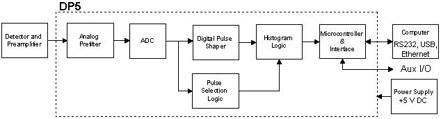
The DP5 is one component in a complete signal processing chain for nuclear instruments. The input to the DP5 is the output of the preamplifier. The DP5 digitizes the output amplifier, applies real-time digital signal processing, determines the amplitude (digital), and stores this value in histogram memory, creating an energy spectrum. The spectrum is then transmitted via the DP5 serial interface to the user's computer. Obviously, the DP5 must be used with other components, including a detector, amplifier, and computer.
Fig. 3. Block diagram of DP5 in a complete system.
Analog input filter
The input to DP5 is the output from the charge-sensitive preamplifier. An analog prefilter circuit prepares this signal for further digitization. The main functions of this circuit are to (1) apply appropriate gain and bias using the dynamic range of the ADC, and (2) perform some filtering and pulse shaping to optimize digitization.
NOTE: The DP5 can be ordered with a charge-sensing preamplifier on board for use with PMTs.
ADC
The ADC digitizes the output analog signal after preliminary filtering at 20 or 80 MHz speed (selectable by software). The digital values are transmitted in real time to the digital pulse generator, which uses a 12-bit ADC.
Digital pulse generator
The ADC output is processed continuously using a pipeline architecture to create a pulse shape in real time. This is done by shaping the pulse just like any other shaper. The pulse shape is fully digitized. It can then be routed to a DAC for diagnostic purposes, but this is not necessary.
There are two parallel signal processing paths inside the DPP - the "fast" and "slow" channels, optimized to obtain different information from the incoming pulses. The "slow" channel, which has a large shaping time constant, is optimized to obtain an accurate pulse height. The maximum value for each pulse in the slow channel is the main output from the pulse shaper. The "fast" channel is optimized to obtain timing information: detecting pulses that overlap in the slow channel, measuring the incoming count rate, measuring the pulse rise time, etc.
The DP5 uses a trapezoidal pulse shape that provides high energy resolution, reduces ballistic deficit, and provides excellent count stability at high count rates.
Pulse selection logic
Pulse selection logic rejects pulses for which measurement accuracy cannot be met. It includes pulse overlap rejection, rise-time discrimination, external gate logic, etc. At high count rates, the DP5 has both better pulse overlap rejection and higher throughput than a traditional analog shaper.
Memory Histogramming
The histogram memory works like a traditional MCA. When a pulse arrives with a certain peak value, the counter in the corresponding memory cell is incremented. The result is a histogram, an array in which each cell contains the number of events with the corresponding peak value. This is the energy spectrum and is the main output of the DP5. The device also includes several counters, counting both the total number of sampled pulses and the number of input pulses, uncounted events, etc. Additional outputs include eight different single-channel analyzers and both a digital-output DAC and a pulse shape display from several points in the signal processing chain.
Interface
The DP5 includes hardware and software for the interface between these various functions and the user's computer. The interface's primary function is to transmit the spectrum to the user. The interface also controls data acquisition, starting and stopping processing, and clearing the memory histogram. It also controls certain aspects of analog and digital shaping, such as setting analog gain or shaping the time pulses.
The interface includes a microcontroller that is compatible with RS232, USB, Ethernet.
PC5 Power and Interface
The Amptek DP5 digital processor is a component in a complete signal processing system for nuclear instrumentation. It can be used with other components, including (at a minimum) a detector and amplifier, and a computer with a serial interface and communications software. The DP5 itself has its own +5 VDC power supply. When using the DP5 with Amptek detectors, no additional power supplies are required for the detector and preamplifier. Amptek provides power via the PC5, which interfaces with the DP5 and provides power to the Amptek detectors.
The PC5 provides power to the Amptek XR-100 detector from a +5VDC source. This board is intended for those using Amptek sensors and preamps. The USB interface cannot provide enough current to operate the XR100, so an external DC source is required and must provide power between 2.5V and 5.5V.
Dimensions: 3.5" x 2.5"
Fig. 4. DP5 with PC5 and Amptek detector/preamplifier.
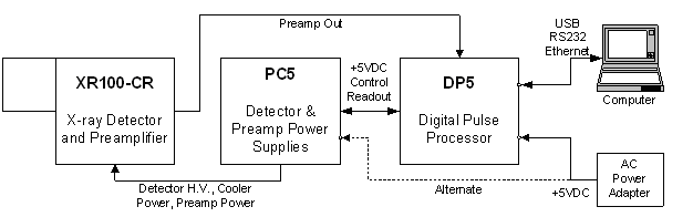
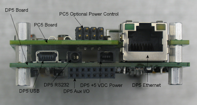
Fig. 5. DP5 (top) paired with PC5 (bottom)

Fig. 6. DP5 (bottom) paired with PC5 (top), rear view
Software
There are two different software packages that are needed for the DP5: the firmware that runs on the microcontroller on the DP5 (firmware), and the software that runs on the included computer.
Embedded software
The embedded software is responsible for controlling the processing of MCA control pulses, performing some data processing and interacting with a personal computer. This software is pre-installed and cannot be changed by the user. Software updates are released by Amptek continuously and can be downloaded by the user.
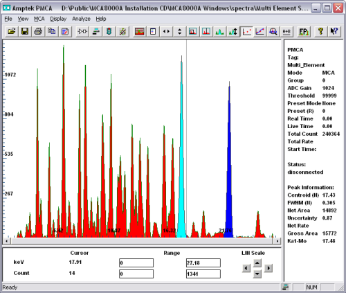
Fig. 7. DPPMCA display and software
Software interface
DPPMCA Software
DP5 can be controlled on the Amptek DPPMCA display via dedicated software. This software can be used to control and display DP5 and supports ROI, calibration, peak search, and so on.
DPP SDK
DP5 comes with a complete software development kit (SDK). The user can use this platform to easily develop their own software to control DP5 for custom applications or to interface it with a larger system. Examples are provided in VB, VC++, etc.
Connecting A250 to DP5, Digital Pulse Processor and MCA
Fig. 9. The A250 charge-sensitive preamplifier is connected to a DP5 or PX5 and an MCA

Connecting a germanium (HPGe) detector to DP5
Fig. 10. DP5 pulse processor connected to a germanium (HPGe) detector. Various materials
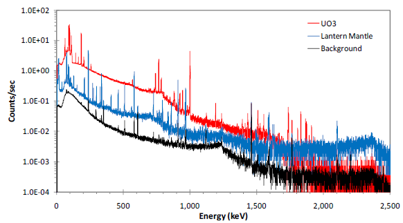
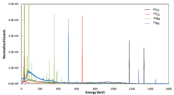
Fig. 11. DP5 pulse processor connected to a germanium (HPGe) detector. Various radioisotopes
DP5G for use with scintillators and photomultipliers
The Amptek DP5G is a high-performance, low-power digital pulse processor designed for use in scintillation spectrometry systems. Attached to the anode of the PMT, it includes a charge-sensitive preamplifier and pulse processor board that replaces both the shaping amplifier and MCA in a traditional nuclear spectroscopy system. The DP5G offers a number of advantages over traditional systems, including higher throughput, increased flexibility, small size, and lower cost.
Fig. 12. DP5G shown at full size, 2" x 1.75"

DP5G is one component in a complete gamma spectrometer system, as shown in the figure below. DP5G includes only the basic signal processing functions. The complete system must also include a module detector (scintillator, PMT, high-voltage power supply, tubes) and an interface circuit with power supplies and connectors for serial connection. Amptek can provide the user with a single DP5G, or can provide a PCG interface module, or can provide a complete system including a module detector. The entire system is a separate Amptek product.
DP5G represents the latest generation in digital pulse processing. DP5G is a variant of DP5 optimized for scintillation counters. DP5 technology includes fast peak time, improved pulse aliasing rejection and pulse shape discrimination, better dead time correction, additional features such as "Mode List" and additional interfaces.


