

EN
X-123SDD Detection System
The X-123SDD is a complete X-ray detection solution with a silicon drift detector in a compact package that fits in your hand.
Without the use of liquid nitrogen
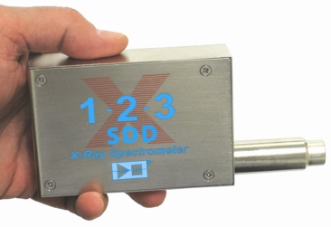
Fig. 1 Spectrometer X-123SDD.
X-123SDD includes
- Silicon Drift Detector (SDD) and Preamplifier
- Digital Pulse Processor and Analyzer
- Power supply and software compatible with your PC
Advantages
- Compactness of the system
- Ease of use
- Small size (7 x 10 x 2.5 cm)
- Low power consumption (2.5W)
- Light weight (180g)
- USB, RS232 and Ethernet connectors
Application
- X-ray fluorescence analysis (XRF)
- RoHS/WEE compliance for instrumentation
- Control of technological processes
- Art and Archaeology
Detector
- Silicon Drift Detector (SDD) for X-ray Detection
- 2-stage thermoelectric cooling
- Area: 25 mm2
- Thickness: 500 microns
- Multilayer collimator
General characteristics
- Resolution: 125-140 keV, FWHM at 5.9 keV
- Optimal energy range: from 1 keV to 40 keV
- Maximum count rate: up to 5.6 x 10⁵ events per second
The X-123SDD is the result of 15 years of development of X-ray detectors by Amptek. The company's philosophy has always been to produce compact, low power consumption, high performance detectors that are easy to operate. The X-123SDD is an example of this philosophy and is a combination of the XR-100SDD silicon drift X-ray detector and its charge sensitive preamplifier; the DP5 digital pulse processor, MCA, software and PC5 power supply in a single housing. And all this requires only +5 V DC and connection to a computer via USB, RS232 or Ethernet.
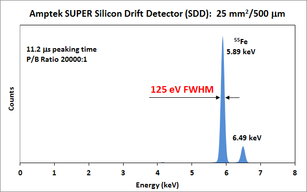
Fig.2 Spectrum of 55Fe obtained using a silicon drift detector (SDD).
Description
The X-123SDD combines Amptek's high-quality X-ray spectrometry components into a single package: (1) an XR-100SDD X-ray detector with preamplifier, (2) a DP5 digital pulse processor with MCA, and (3) a PC5 power supply. The result is a complete system that fits in your hand without sacrificing performance. The X-123SDD requires only +5VAC and a standard PC connection to operate. With the X-123, anyone can quickly acquire high-quality X-ray spectra.
The X-123SDD uses a silicon drift detector (SDD) similar to a Si-PIN photodiode, but with a unique electrode structure that provides better resolution and counting speed. The SDD is mounted on a thermoelectric cooler with an input field-effect transistor and is connected to a charge-sensitive preamplifier. Thermoelectric cooling reduces the level of electrical noise in the detector and preamplifier, but at the same time the cooling remains open and understandable to the user: it works like a conventional air conditioning system.
The DP5 Pulse Processor is a second generation digital pulse processor (DPP) that replaces both the signal amplifier and the multichannel analyzer (MCA) found in similar systems. The use of digital technology provides improvements in the following key parameters: (1) better performance, such as better resolution and higher count rate; (2) excellent flexibility in configuring settings selected via software; (3) improved stability and reproducibility of results. The DPP digitizes the output signal from the preamplifier using real-time digital signal processing, detects the peak amplitude and collects these values in memory histograms, generating an energy spectrum. The spectrum is then transferred to the user's PC. The PC5 provides power to the detector, low voltage to the preamplifiers and high bias voltage to the detector, and powers the thermoelectric cooling, which provides a closed-loop control with a maximum temperature difference of 85 °C. All this is controlled by the provided software. X-123SDD is powered by +5V with a current of about 300 mA.
The entire system is housed in an aluminum housing measuring 7 x 10 x 2.5 cm 3 . The detector is mounted on an extension cable ranging from 0 to 22.86 cm in length (vacuum flanges are available). In the standard configuration, only 2 connections are required: power supply (+5V) and a PC connection (USB, RS232 or Ethernet). Several additional inputs and outputs are also available if the X123 is integrated with other equipment. This includes a multi-channel analyzer chain and selective signal memory, time control and a single-channel analyzer. The X-123SDD comes complete with data acquisition and control software. It also includes a DLL application programming interface (API) for integrating the unit with custom software. Software for X-ray spectrum analysis, vacuum hardware, several collimator and mounting options, and X-ray tubes can be optionally added to create a complete compact XRF system.
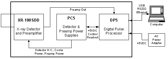
Fig.3 Block diagram of X-123SDD and connection diagram.
Characteristics of X-123SDD
|
General |
|||||||||||||||||||||||||||||||||||||
|
Energy resolution |
125 - 140 eV (full width at half maximum) at 5.9 keV. Dependent on peak time and temperature. |
||||||||||||||||||||||||||||||||||||
|
Electrical noise level |
73 eV (width at half maximum) |
||||||||||||||||||||||||||||||||||||
|
Signal to Noise Ratio |
20,000:1 (counting ratio from 5.9 keV to 1 keV) |
||||||||||||||||||||||||||||||||||||
|
Energy range |
Efficiency >25% for X-rays with energies from 1 to 25 keV. Can operate outside this range, but with lower efficiency. |
||||||||||||||||||||||||||||||||||||
|
Maximum counting speed |
Depends on peak time. Recommended parameters are presented in the table below:
|
||||||||||||||||||||||||||||||||||||
|
Detector and preamplifier |
|||||||||||||||||||||||||||||||||||||
|
Detector type |
Silicon Drift Detector (SDD) |
||||||||||||||||||||||||||||||||||||
|
Detector area |
25 mm2 (collimator area 17 mm2) |
||||||||||||||||||||||||||||||||||||
|
Detector thickness |
500 microns |
||||||||||||||||||||||||||||||||||||
|
Thickness Be of the window |
0.5 mil (12.5 µm) |
||||||||||||||||||||||||||||||||||||
|
Collimator |
Multilayered |
||||||||||||||||||||||||||||||||||||
|
Thermoelectric cooling |
2-stage (ΔTmax=85°) |
||||||||||||||||||||||||||||||||||||
|
Preamplifier type |
Charge sensitive, manufactured by Amptek. |
||||||||||||||||||||||||||||||||||||
|
Preamplifier Conversion Ratio |
1 mV/keV (typical) |
||||||||||||||||||||||||||||||||||||
|
Digital Pulse Processor (DPP) |
|||||||||||||||||||||||||||||||||||||
|
Gain |
Combination of coarse and fine gain provides continuous gain from 0.84 to 127.5 |
||||||||||||||||||||||||||||||||||||
|
Rough amplification |
Software selectable from 1.12 to 102.0 in 16 steps: 1.12, 2.49, 3.78, 5.26, 6.56, 8.39, 10.10, 11.31, 14.56, 17.77, 22.42, 30.83, 38.18, 47.47, 66.26, 102.0 |
||||||||||||||||||||||||||||||||||||
|
Subtle enhancement |
Software selectable from 0.75 to 1.25, with 10-bit resolution. |
||||||||||||||||||||||||||||||||||||
|
Full scale |
1000 mV input pulse at X1 gain |
||||||||||||||||||||||||||||||||||||
|
Stability |
<20 ppm/°C (typical) |
||||||||||||||||||||||||||||||||||||
|
Pulse shape |
Trapezoidal (A semi-Gaussian amplifier with shaping time t has a peak time of 2.2t and is comparable to a trapezoidal shape of the same peak time) |
||||||||||||||||||||||||||||||||||||
|
ADC clock frequency |
From 20 to 80 MHz |
||||||||||||||||||||||||||||||||||||
|
Peak time |
30 different software selectable values from 0.2 to 102 µs, corresponding to semi-Gaussian shaping times from 0.1 to 45 µs. |
||||||||||||||||||||||||||||||||||||
|
Plateau |
16 software selectable values for each peak time (peak time dependent), >0.05 µs. |
||||||||||||||||||||||||||||||||||||
|
Recovery |
Asymmetric, 16 software-selectable convolution rates. |
||||||||||||||||||||||||||||||||||||
|
Two-pulse resolution time |
120 nano seconds |
||||||||||||||||||||||||||||||||||||
|
Dead time |
1.05 peak time. No conversion time. |
||||||||||||||||||||||||||||||||||||
|
Maximum counting speed |
4x10 6 s-1 |
||||||||||||||||||||||||||||||||||||
|
Dead Time Adjustment |
Manual adjustment. Accuracy up to 1%. |
||||||||||||||||||||||||||||||||||||
|
Pulse selection options |
Overlap rejection, sorting by rise time, pass-through |
||||||||||||||||||||||||||||||||||||
|
Multi-Channel Analyzer (MCA) |
|||||||||||||||||||||||||||||||||||||
|
Number of channels |
Software selectable: 8,000; 4,000; 2,000; 1,000; 500; or 250 channels |
||||||||||||||||||||||||||||||||||||
|
Bytes per channel |
3 Bytes (24 bits) - 16.7x 10⁶ signals |
||||||||||||||||||||||||||||||||||||
|
Opening hours |
From 10 ms to 466 days |
||||||||||||||||||||||||||||||||||||
|
Data transfer time |
1,000 channels in 12 ms (USB) or 280 ms (RS-232) |
||||||||||||||||||||||||||||||||||||
|
Conversion time |
Missing |
||||||||||||||||||||||||||||||||||||
|
Preset |
Time, total number of invoices, number of invoices per ROI, number of invoices transmitted via 1 channel |
||||||||||||||||||||||||||||||||||||
|
MCS Time Base |
From 10 ms/channel to 300 s/channel |
||||||||||||||||||||||||||||||||||||
|
External MCA controls |
Input: Pulse is passed only when the pass is allowed by the external logic system. Software controlled. |
||||||||||||||||||||||||||||||||||||
|
Auxiliary I/O channels |
|||||||||||||||||||||||||||||||||||||
|
Single Channel Analyzer (SCA) |
8 SCA |
||||||||||||||||||||||||||||||||||||
|
Digital output |
Two independent outputs with 8 programmable settings: INCOMING_COUNT, PILEUP, MCS_TIMEBASE, etc. |
||||||||||||||||||||||||||||||||||||
|
Digital input |
Two independent inputs, software selectable from MCA_GATE, EXTERNAL_COUNTER |
||||||||||||||||||||||||||||||||||||
|
I/O |
Two common I/O lines for user application |
||||||||||||||||||||||||||||||||||||
|
Digital oscilloscope |
The oscilloscope data is displayed on the computer. The software selects whether to show the output signal shape, the input signal to the ADC, etc. They are used for debugging equipment. |
||||||||||||||||||||||||||||||||||||
|
Connectors |
|||||||||||||||||||||||||||||||||||||
|
USB |
USB 2.0 (12 Mbps) |
||||||||||||||||||||||||||||||||||||
|
Serial |
Standard RS232 |
||||||||||||||||||||||||||||||||||||
|
Ethernet |
10base-T |
||||||||||||||||||||||||||||||||||||
|
Nutrition |
|||||||||||||||||||||||||||||||||||||
|
Nominal input |
+5 VDC at 500 mA (2.5 W) (typical). Current is highly dependent on the detector's ΔT. Range is 300 to 800 mA at 5 VDC. AC adapter included. |
||||||||||||||||||||||||||||||||||||
|
Input voltage range |
From 4 V to 5.5 V (at currents of 0.4 - 0.7 A) |
||||||||||||||||||||||||||||||||||||
|
The beginning of the transition process |
2 A for <100 µs |
||||||||||||||||||||||||||||||||||||
|
High voltage |
Internal multiplier, software controlled, from -95 to -1500V |
||||||||||||||||||||||||||||||||||||
|
Cooling power supply |
Feedback controller ΔTmax = 85 °C |
||||||||||||||||||||||||||||||||||||
|
Overall dimensions |
|||||||||||||||||||||||||||||||||||||
|
Dimensions |
7 x 10 x 2.5 cm, excluding extension |
||||||||||||||||||||||||||||||||||||
|
Length of extension |
3.8 cm |
||||||||||||||||||||||||||||||||||||
|
Weight |
180 g |
||||||||||||||||||||||||||||||||||||
|
General |
|||||||||||||||||||||||||||||||||||||
|
Operating temperature |
From -20 %C to +50 %C |
||||||||||||||||||||||||||||||||||||
|
Guarantee |
1 year |
||||||||||||||||||||||||||||||||||||
|
Average service time |
5 - 10 years, depending on use |
||||||||||||||||||||||||||||||||||||
|
Storage and transportation |
Long shelf life: 10+ years in dry environment Typical Storage and transport: -20°C to +50°C, 10 to 90% humidity non-condensing |
||||||||||||||||||||||||||||||||||||
|
Correspondence |
RoHS compliant |
||||||||||||||||||||||||||||||||||||
|
TUV Certification Certificate No.:CU 72101153 01 Tested to: UL 61010-1: 2009 R10.08 CAN/CSA-C22.2 61010-1-04 + Gi1 |
|||||||||||||||||||||||||||||||||||||
|
Connectors |
|||||||||||||||||||||||||||||||||||||
|
USB |
Standard USB Mini connector. (The X-123SDD is not USB powered.) |
||||||||||||||||||||||||||||||||||||
|
RS232 |
Standard 2.5mm headphone jack. TipTransmitFor PC Receive DB9 pin 2 (to DB25 pin 3)RingReceiveFor PC Transmit DB9 pin 3 (to DB25 pin 2)SleeveGroundFor PC Ground DB9 pin 5 (to DB25 pin 7) |
||||||||||||||||||||||||||||||||||||
|
Ethernet |
Standard Ethernet connector (RJ-45) |
||||||||||||||||||||||||||||||||||||
|
Nutrition |
Hirose MQ172-3PA (55), Plug Mating: MQ172-3SA-CV |
||||||||||||||||||||||||||||||||||||
|
Auxiliary |
2x8 16-pin 2mm (Samtec part number ASP-135096-01). Mates with Samtec P/N TCMD-08-S-XX.XX-01. Top row odd contacts, bottom row even contacts. Top right contact = 1, bottom right contact = 2.
|
||||||||||||||||||||||||||||||||||||
|
Software interface |
|||||||||||||||||||||||||||||||||||||
|
DPPMC |
The X-123SDD can be controlled by the Amptek DPPMCA display and dedicated software. This program completely controls and configures the X-123, acquires and displays the data. It supports ROI, calibration, peak search, etc. The DPPMCA software includes an interface for XRF analysis and a software package. It runs under Windows XP PRO SP3 or later. |
||||||||||||||||||||||||||||||||||||
|
SDK |
X-123SDD comes with a free software development kit (SDK). The user can use this kit to write their own code to control X-123SDD to solve their own problems. |
||||||||||||||||||||||||||||||||||||
|
VB demo software |
The VB demo software runs on a personal computer and allows the user to configure the X-123SDD, start and stop data collection, and save data files. It comes with source code and can be modified by the user. This software is intended to demonstrate how to control the X-123SDD manually or via the USB or RS-232 interface using basic commands without an SDK. This is primarily needed when writing software for non-Windows platforms. |
||||||||||||||||||||||||||||||||||||
Option
- Other beryllium window thicknesses are available upon special order (0.3 mil - 7.5 µm).
- A set of collimators for working with large flows.
- Vacuum equipment
- Can be used as a component of OEM systems
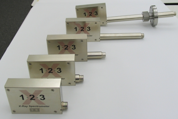
Fig.4 X-123SDD in extended versions.
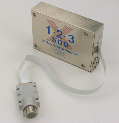
Fig.5 X-123 with PA-230 preamplifier in the case. This option is similar to the X-123 detector itself, except that the detector/preamplifier is removed from the electronics case and connected to it via a flexible cable.
Working in a vacuum
The X-123SDD can operate in both air and vacuum at pressures up to 10-8 Torr. There are two options for operating the X-123SDD in vacuum: 1) The entire X-123SDD detector and preamplifier can be placed inside the chamber. In order to avoid overheating and dissipating the 1 W of power required to operate the X-123SDD, good thermal conductivity to the chamber walls must be ensured using four mounting holes. 2) The X-123SDD can be located outside the vacuum chamber, a standard ConFlat port is used for X-ray detection in the chamber.
Additional information about the system
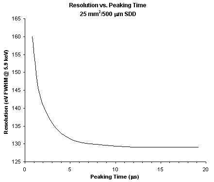
Fig.6 Plot of resolution versus peak time for a silicon drift detector (SDD).
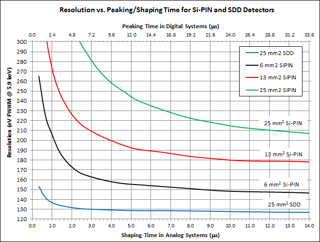
Fig.7 Resolution dependence on Formation time/Peak time for Si-PIN and SDD detector.
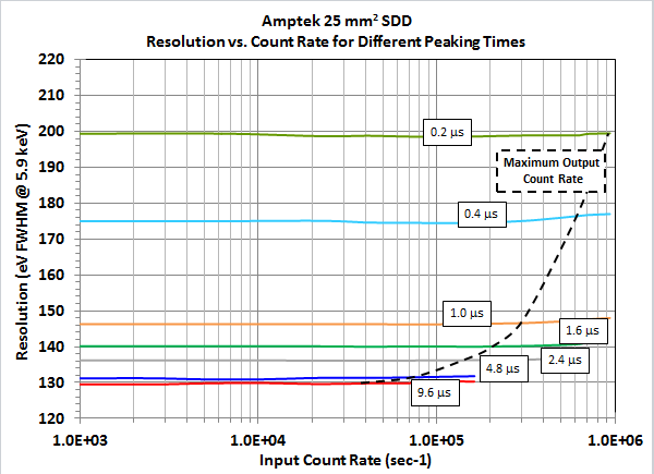
Fig.8 Resolution versus count rate for different peak times.
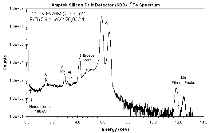
Fig.9 Spectrum of 55Fe from 4 million measurements obtained with a silicon drift detector (SDD).
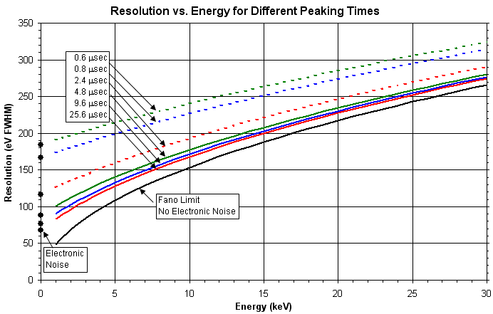
Fig.10 Plot of resolution versus energy for different peak times obtained with a silicon drift detector (SDD).
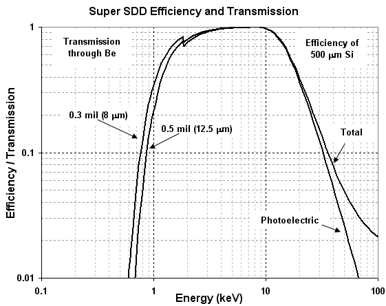
Fig.11 The figure combines the effect of beryllium glass permeability (including the protective layer) and interaction with the SDD detector. The low-energy region on the graph is determined by the thickness of the beryllium glass - 0.3 mil (8 μm) or 0.5 mil (12.5 μm), while the high-energy region is characterized by the thickness of the active zone of the SDD detector.
Additional spectra
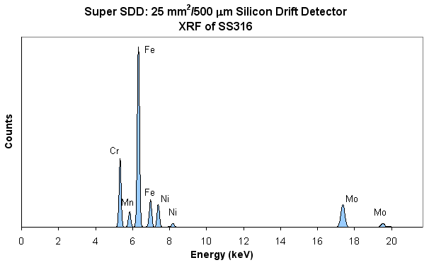
Fig.12 XRF of SS316 stainless steel obtained using a silicon drift detector (SDD) and a Mini-X X-ray tube.
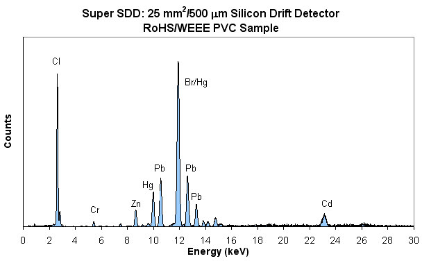
Fig.13 Spectrum obtained for RoHS/WEEE PVC sample using Super SDD detector and Mini-X X-ray tube.
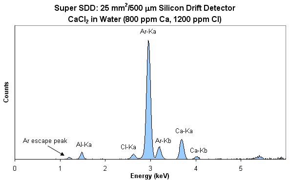
Fig.14 Spectrum of CaCl2 (800 ppm Ca and 1200 ppm Cl).
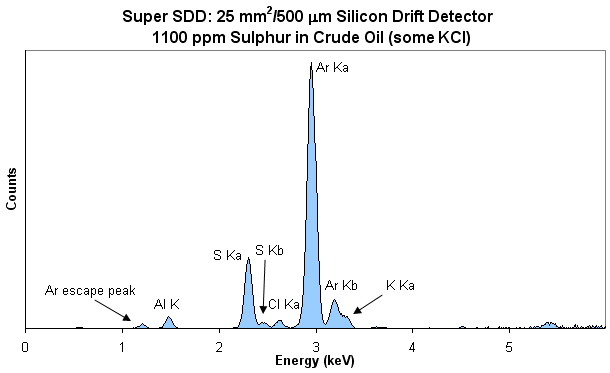
Fig.15 Sulfur in crude oil (1100 ppm) with a small proportion of KCl.
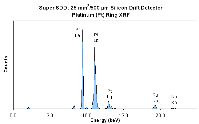
Fig. 16 XRF of a platinum (Pt) ring.
Structural dimensions
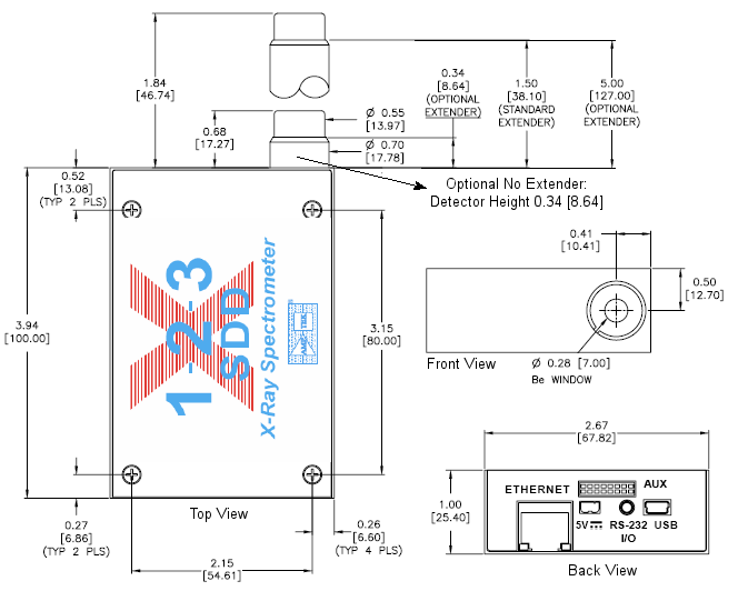
Fig.17 Dimensions: inches [millimeters].
Fasteners
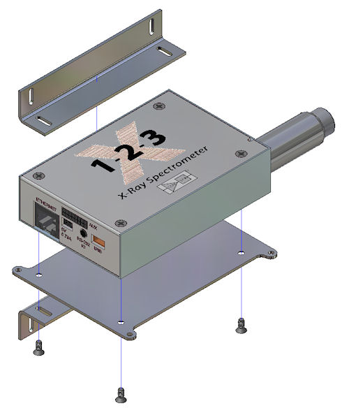
Fig.18 X-123SDD comes with two types of fasteners: rectangular and flat.
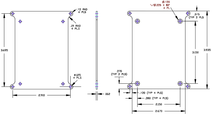
Fig.19 X-123 flat fastener.
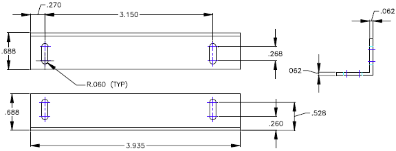
Fig.20 X-123 rectangular fastener.
Full-fledged XRF system
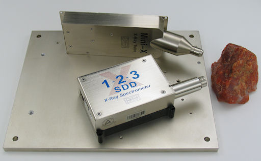
Fig.21 Complete XRF system. X-123SDD and Mini-X mounted on a flat MP1 mount.
The experimental XRF system consists of:
- X-123SDD
- Mini-X - USB controlled X-ray tube
- XRF-FP — software for qualitative analysis
- MP1


